

A pneumatic suction gripper lifts and holds parts by using vacuum created from compressed air. Before you size a gripper for a robot arm or an automation line, you must know exactly how much force it can safely hold. This guide walks through the holding force formula, a worked example using real product dimensions, and the real-world factors that eat into rated capacity — so your payload stays secure and your cycle time stays predictable.
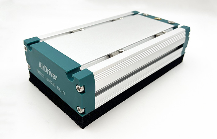
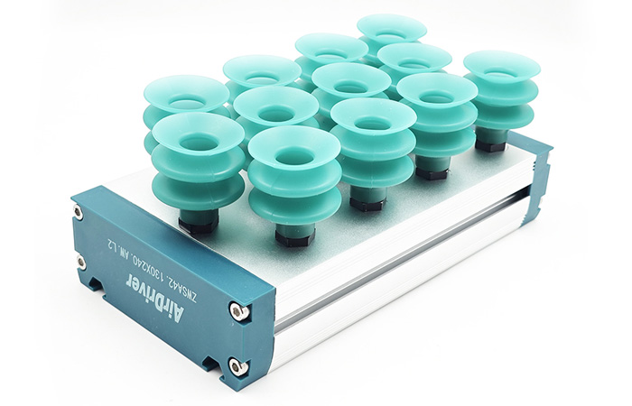
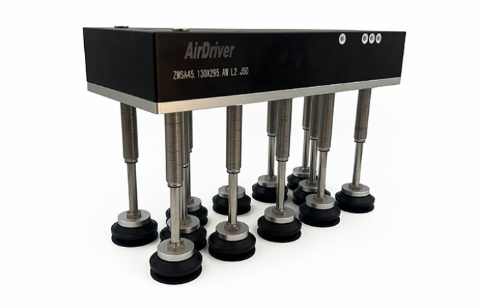
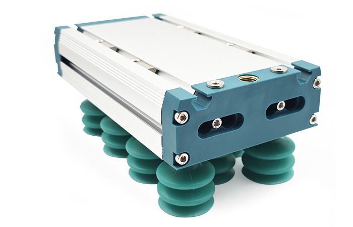
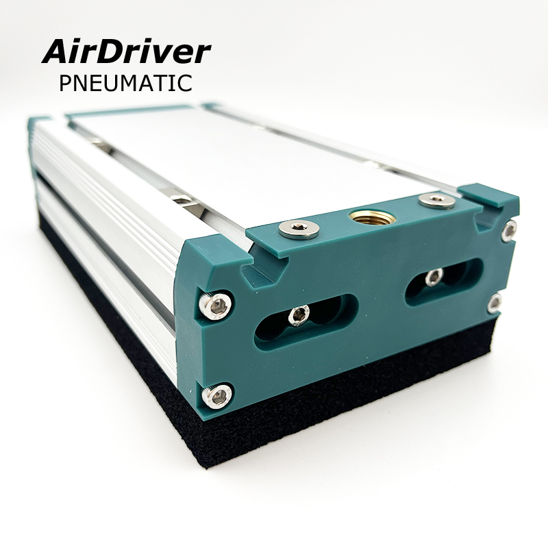
A pneumatic suction gripper is a vacuum-based end-effector that uses a venturi vacuum generator to pull air out of a sealed suction area. The pressure difference between the atmosphere and the vacuum chamber produces a net force that clamps the workpiece against the gripper face. AirDriver builds these as compact, integrated units — such as the ZWSA foam vacuum gripper — with a built-in generator, a one-way check valve, and a leakproof sponge pad that conforms to irregular surfaces.
Because the force comes from air pressure rather than mechanical jaws, a suction gripper can handle fragile, flat, curved, or porous parts without marking them. That makes it a staple in packaging, electronics, photovoltaic, and lithium-battery automation.
AirDriver has manufactured pneumatic automation components since 2018, operating a 10,099 m² plant with 8 assembly lines and 200+ staff. The figures and examples below are drawn from grippers we build and validate on real production cells, not from generic assumptions.
Holding force is the maximum load a gripper can support before the part detaches. It is the single number that decides whether your pick-and-place cycle is safe or risky. Two loading directions matter:
● Normal (pull-off) force — the load pulls straight away from the gripper face, such as lifting a panel vertically.
● Shear (side) force — the load tries to slide parallel to the face, such as carrying a part sideways. Shear capacity is far lower because it depends on friction, not vacuum alone.
Underestimating holding force causes dropped parts, damaged product, and unsafe cells. Overestimating wastes payload budget on oversized generators and slower cycles. A correct calculation lands in the middle.
The theoretical holding force of any vacuum gripper follows one equation:
F = ΔP × A
| Symbol | Meaning | Unit |
|---|---|---|
| F | Theoretical holding force | Newton (N) |
| ΔP | Pressure difference (vacuum level below atmosphere) | Pascal (Pa) |
| A | Effective sealed suction area | Square metre (m²) |
For multiple suction points, multiply by the number of cups:
Ftotal = ΔP × A × N
Atmospheric pressure is about 101.3 kPa. A venturi that reaches −60 kPa gauge means ΔP = 60,000 Pa. The effective area is the real contact area that seals — for a round cup, π × r²; for a rectangular foam vacuum gripper pad, the full pad footprint that touches the part.
Let us size a gripper for a 30 kg carton on a ZWSA sponge pad model with a 130 mm × 240 mm pad, running at −60 kPa vacuum.
| Step | Calculation | Result |
|---|---|---|
| Effective area (A) | 0.130 m × 0.240 m | 0.0312 m² |
| Pressure difference (ΔP) | 60 kPa | 60,000 Pa |
| Theoretical force (F) | 60,000 × 0.0312 | 1,872 N |
| Safe load (SF = 2) | 1,872 ÷ 2 | 936 N (≈ 95 kg) |
The 30 kg carton needs about 294 N of safe holding force (30 × 9.81). At 936 N safe capacity, this pad has roughly 3.2× margin — comfortable, but remember the safety factor already builds in leakage and acceleration. For a small 50 mm round cup at the same vacuum, theoretical force drops to about 118 N (≈ 59 N safe), showing why pad size drives capacity far more than vacuum level alone.
Browse the full AirDriver vacuum gripper range, including the ZWSA foam model and bellows suction cups, to match pad size and vacuum flow to your part weight.
The formula gives the ideal number. On the factory floor, several effects cut the usable force. Build these into your safety factor:
● Surface leakage — porous, rough, or curved parts let air leak in, lowering ΔP. Sponge pads seal better than rigid cups here.
● Acceleration and inertia — fast robot moves add dynamic load; a 2–4× safety factor covers this.
● Shear vs normal — sideways carrying only holds μ × the normal force, where μ is 0.1–0.5 by surface.
● Vacuum source and tubing — long lines and small generators drop pressure; size the pneumatic supply to hold target ΔP at the cup.
Both use the same F = ΔP × A law, but the effective area and seal behaviour differ. A bellows suction cup seals a small defined circle and excels on flat, non-porous parts. A sponge pad spreads suction across a large, compliant footprint, sealing gaps on uneven or porous workpieces — so it often wins on irregular loads even at similar vacuum.
| Factor | Bellows Suction Cup | Sponge / Foam Pad |
|---|---|---|
| Best surface | Flat, smooth, non-porous | Uneven, curved, porous |
| Effective area | Cup mouth only | Full pad footprint |
| Leak tolerance | Low | High (adaptive seal) |
Start from your part weight, then work backwards: pick the vacuum level your generator can hold, size the pad or cup area from the formula, multiply by the number of points, and divide by a 2–4× safety factor. If the part is porous or odd-shaped, a sponge pad typically needs less area than a rigid cup to hit the same safe load. For the physics behind the seal, see our explainer on how vacuum grippers work.
We built a holding-force calculator that turns vacuum level, pad size, cup count, and safety factor into a safe working load in seconds. Open it, then match the result to a ZWSA model.
Q: What is the holding force of a pneumatic suction gripper?
A: It equals the pressure difference (ΔP) multiplied by the effective sealed area (A), or F = ΔP × A. A typical −60 kPa venturi on a 0.03 m² pad gives about 1,800 N theoretical, roughly 90 kg of safe working load at a 2× safety factor.
Q: How do you calculate vacuum gripper holding force in kg?
A: Compute force in Newtons with F = ΔP × A, then divide by 9.81 to get kilograms. Always divide that result again by your safety factor (usually 2–4) before trusting it as a working load.
Q: What vacuum level is needed for a given weight?
A: Rearrange the formula: ΔP = (mass × 9.81 × safety factor) ÷ A. A 20 kg part on a 0.02 m² pad with a 2.5× factor needs about 24.5 kPa of vacuum — well within a standard venturi’s range.
Q: Does holding force change for vertical vs horizontal lifting?
A: Vertical lift uses the full normal force. Horizontal carrying is a shear load and only holds roughly the friction coefficient (μ = 0.1–0.5) times the normal force, so it is much weaker and needs more cups or area.
Q: How does a sponge or foam gripper affect holding force vs a suction cup?
A: The physics is identical, but a foam pad seals a larger, compliant area and tolerates leaks on uneven parts. On irregular loads it often reaches the same safe force with less vacuum than a rigid cup.
Q: What safety factor should I use for pneumatic suction grippers?
A: Use 2× for stable, slow, vertical lifts on clean surfaces. Use 3–4× for fast robot moves, porous parts, side loads, or any application where a drop would be costly or dangerous.
Q: How many suction cups do I need for my payload?
A: Divide your required safe force (mass × 9.81 × safety factor) by the force of one cup at your vacuum level, then round up. Spreading load across several small cups also improves stability versus one large pad.
Q: Can a pneumatic suction gripper hold porous or uneven surfaces?
A: Yes, especially foam or sponge models with adaptive sealing and a check valve that holds vacuum locally. Rigid cups struggle on leaks, so choose pad type by surface before sizing area.
Tell us your part weight, surface, and cycle speed. Our engineers will recommend the right ZWSA pad size, vacuum flow option, and safety margin for your cell.
● Exploring the Mechanics of Vacuum Grippers: How Do They Work? — the seal, venturi, and release physics behind every suction gripper.
● Pneumatic Cylinder Actuator: Essential Components for Efficient Automation Systems — sizing the air supply that feeds your gripper.
● AirDriver Vacuum Gripper Product Category — foam pads, bellows cups, and pneumatic models for every payload.