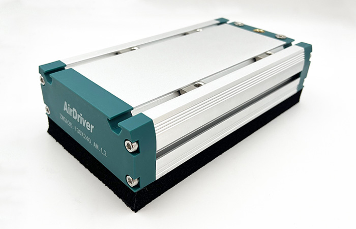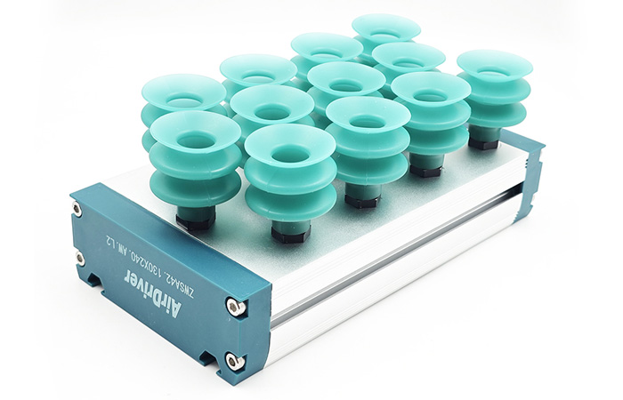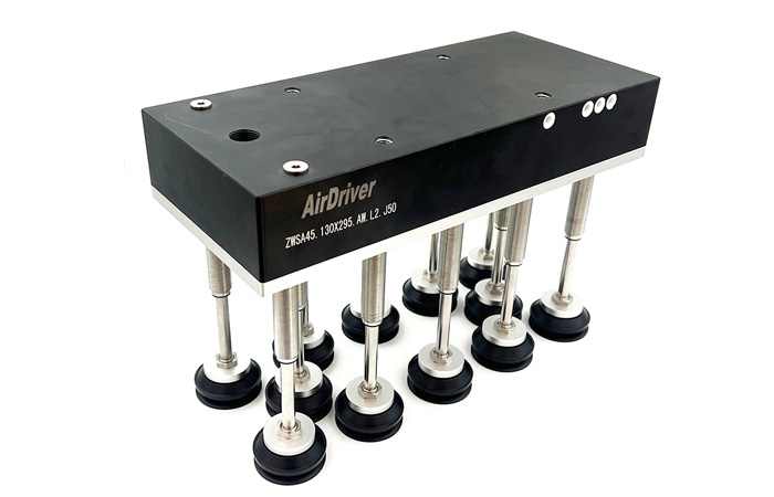


A pneumatic suction gripper holds a workpiece with nothing but a pressure difference. No jaw closes around the part, no clamp locks it in place. That is exactly why these grippers are fast, gentle on surfaces and economical to run on packaging, palletizing and robot handling lines — and also why a single lost seal turns into a dropped load.
In practice, most gripper incidents are not caused by exotic failures. They come from predictable, repeatable causes: supply pressure that dips when a neighbouring machine fires, a cup lip that has quietly worn past its useful life, an array sized on static weight with no margin for acceleration, or a vacuum switch that was never interlocked with the robot motion. Every one of those is preventable at the design stage or caught by a routine check.
This guide covers the eight safety checks that matter before and during operation, the failure patterns we see most often on production lines, and how to specify an industrial pneumatic suction gripper that stays safe across millions of cycles. It is written for maintenance engineers, automation integrators and procurement teams who need to justify a specification, not just a part number.
Quick answer: a pneumatic suction gripper operates safely when three conditions hold at the same time. First, the vacuum measured at the cup stays above the minimum required for the worst-case load. Second, the rated holding force carries a safety factor of at least 2.0 for horizontal transfer and 4.0 or higher for vertical or overhead moves. Third, a loss of vacuum is detected and interlocked before the part can be released. Cup material, filtration, installation quality and maintenance intervals all exist to protect those three conditions.
Compressed air is the input and vacuum is the output. If supply pressure sags, the ejector produces less vacuum, and the gripper holds less than its rating. Measure supply pressure at the point of use — at the air preparation unit on the machine, not at the compressor gauge thirty metres away — and confirm it holds value through the full cycle, including the moment other equipment on the same line actuates.
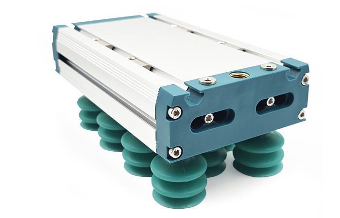
Then measure vacuum at the cup, not at the generator. A reading taken at the ejector can look healthy while a restriction or a marginal seal downstream costs you 10–20 per cent of the force that actually reaches the workpiece. Fit a vacuum gauge or a digital vacuum switch at the gripper and record the value during a dry run with the real part at full cycle speed. That number becomes your baseline, and every later check is compared against it.
Cup geometry and elastomer decide whether a seal forms at all. Flat cups suit flat, smooth, rigid surfaces such as glass, sheet metal and plastic panels. Bellows cups handle curved, uneven or height-varying surfaces because the folds absorb the difference. Foam or sponge pads are the practical answer for porous or gappy workpieces — woven bags, cartons, rough castings — where a standard cup never achieves a seal.
Material matters just as much. NBR is the general-purpose choice, silicone covers food contact and higher temperatures, and polyurethane resists abrasion when parts are rough or slide during placement. Matching cup to surface is not a performance tweak: a cup that only partially seals bleeds vacuum continuously, and the part may lift and then release mid-move. When you review options, check the full vacuum suction cups range against your surface finish and operating temperature rather than reusing whatever was fitted to the previous machine.
The theoretical holding force of a cup is its effective area multiplied by the pressure difference. That figure is a starting point, never the design number. Real holding capacity has to absorb dynamic loads: robot acceleration, deceleration, direction changes, emergency stops, and the shear forces that appear when a part is carried on a vertical face.
The usual industry practice is a safety factor S of at least 2.0 for horizontal transfer and 4.0 or more for vertical or overhead handling, rising further whenever the load travels above people, the surface is oily or dusty, or the cycle involves hard acceleration. Never size against the theoretical maximum vacuum; size against the lowest vacuum you measured during the actual cycle.
Also distinguish pull-off from shear. Vacuum resists force perpendicular to the cup face very well. Force parallel to the face is resisted only by friction between cup and workpiece, so the required holding force rises as the friction coefficient drops. Contaminated or wet surfaces are the classic case where a gripper that passed a static test drops the part during a fast move.
Leaks come from four places: a worn or nicked cup lip, cracked or loose tubing and fittings, contamination on the sealing surface, and porous workpieces that bleed air by design. The risk is rarely one dramatic failure. It is a slow leak that holds vacuum just above the switch threshold until the day it does not.
Design the array so a single bad cup cannot take down the whole gripper. A vacuum one-way check valve per cup isolates the failed branch and lets the remaining cups keep their vacuum. For short supply interruptions, a vacuum reservoir or a non-return valve at the ejector buys enough time for the machine to stop in a controlled way, while an inline vacuum filter keeps dust and debris out of the generator.
Finally, decide what happens when the air supply fails completely. On a horizontal transfer the part simply sits down. On an overhead or vertical axis, gravity takes over. If a falling part creates a hazard, add mechanical retention or a secondary holding device — do not rely on the vacuum circuit alone.
Installation quality shows up as response time. Long, narrow tubing restricts flow, which slows vacuum build-up and delays the part-present signal, so the robot starts moving before the part is properly held. Keep vacuum lines short, cut tube ends square, and seat push-in fittings fully.
Mechanically, the gripper must be rigid. Any flex in the bracket changes the cup angle under load and breaks the seal. Set cup heights so all cups contact at the same time, and use spring plungers or level compensators where the workpiece height varies. Route hoses away from sharp edges, heat sources and moving axes, add strain relief where the harness crosses a robot joint, and torque mounting bolts to specification with threadlocker on vibrating equipment.
Inspection only works when it is scheduled against a baseline. Record the achievable vacuum at commissioning, then trend it: a slow downward drift is the earliest and cheapest warning you will get. The intervals below suit a typical multi-shift operation and should be tightened for dusty, abrasive or high-duty applications.
| Item | Interval | What to check |
|---|---|---|
| Vacuum level at the cup | Every shift | Compare with the commissioning baseline; investigate any drop |
| Suction cup lip condition | Daily to weekly | Cuts, cracks, permanent flattening, glazing, dust build-up |
| Tubing and push-in fittings | Weekly | Kinks, abrasion, loose connections, audible leaks |
| Vacuum filter element | Monthly | Clogging, contamination, water accumulation |
| Mounting bolts and brackets | Monthly | Torque, hairline cracks, loosening from vibration |
| Ejector and exhaust silencer | Quarterly | Silencer clogging, drop in achievable vacuum level |
Pick-and-place logic should never run on timing alone. Fit a vacuum switch or a digital display pressure switch with teach-in thresholds and set two levels: one that confirms the cup has sealed, and a higher one that confirms the part is firmly held. Interlock both with the motion controller so the axis cannot start — and cannot continue — unless vacuum is present.
Monitor continuously through the move, not just at the moment of pick. A seal that fails two seconds into a transfer is the failure that causes the damage. On multi-cup arrays, either group cups into monitored branches or fit per-branch check valves so a partial loss is visible instead of silent. Trend the logged values: a slow downward drift in achievable vacuum usually predicts a fault days before an alarm ever fires.
Temperature changes elastomer behaviour. Heat softens cup lips and accelerates wear; cold stiffens them and makes cracking more likely. Choose the compound for the actual operating range rather than the nominal one — a cup that performs well at 20°C can fail within weeks next to an oven or inside a cold store.
Dust, oil mist and humidity each need a response: filtration and more frequent cleaning in dusty cells, oil-resistant compounds where lubricant mist is present, stainless fittings and proper drainage in washdown areas. In food and pharmaceutical lines, specify food-grade silicone and a design that can actually be cleaned, with no dead pockets. Ultraviolet exposure degrades some compounds outdoors, which matters for loading bays and yard-side equipment.
Not sure whether your current gripper array still holds a safe margin?
Send us the workpiece weight, surface condition, cycle time and mounting orientation. AirDriver application engineers will return a sizing calculation with the recommended cup layout and the safety factor stated in writing.
Every gripper line eventually shows one of four failure patterns. Recognising them early turns a safety incident into a maintenance ticket.
What it looks like: parts slip or drop during acceleration, vacuum sits close to the switch threshold, and picks fail intermittently depending on where the part sits in the stack.
Why it happens: the ejector is undersized for the total cup volume, supply pressure drops below the rated value, the vacuum line is restricted, the effective cup area is too small, or the workpiece is porous.
What to do: measure vacuum at the cup under the real cycle. If supply pressure is the problem, check the regulator and the distribution network and confirm capacity at the point of use with correctly sized air preparation units (FRL). If the generator is the limit, move up to a higher-flow vacuum generator or increase effective cup area. Then re-check the safety factor with the new numbers.
What it looks like: visible nicks or flattening on the lip, a black residue ring on the workpiece, vacuum that decays slowly instead of holding, and a rising rate of re-picks.
Why it happens: abrasion from rough surfaces, chemical or ozone attack, the wrong compound for the temperature, or simply no defined replacement schedule.
What to do: replace cups on a cycle count or fixed interval, not on appearance — a lip can look acceptable and still have lost most of its sealing ability. Keep a spare lip set on the line, switch to polyurethane for abrasive parts and silicone for temperature extremes, and record change dates so you can identify the interval that actually works.
What it looks like: no-pick alarms that cluster at peak production, vacuum readings that fluctuate between cycles, and a gripper that behaves differently on the night shift.
Why it happens: an undersized compressor or distribution pipework, simultaneous consumers on the same branch, regulator drift, or general leakage in the plant network.
What to do: give the cell its own regulator, add an air tank close to the gripper to buffer demand peaks, and log pressure at the point of use for a full shift. Fix distribution leaks — they are usually the cheapest capacity increase available. Add a supply pressure switch so the machine stops safely instead of attempting a weak pick.
What it looks like: the gripper passes a bench test and fails in production, cups leave marks or deform the part, and the cycle has to be slowed down to make the pick reliable.
Why it happens: selection based on static weight alone, with acceleration, surface condition, orientation and duty cycle left out of the calculation.
What to do: re-run the sizing with dynamic loads and the correct safety factor, then validate with the real workpiece at production speed. If you do not have the calculation in writing, ask the supplier for it — a manufacturer that cannot explain the numbers is not a safe choice for a load-bearing component.
Selecting an industrial pneumatic suction gripper is a specification exercise, not a catalogue lookup. Three inputs decide the outcome.
Start with what the cup has to seal against. A smooth, non-porous surface — glass, metal sheet, rigid plastic — allows a small flat cup at a high vacuum level. Cardboard and other slightly rough surfaces need a softer lip and more effective area. Genuinely porous workpieces such as woven bags, fabric, wood or open-cell foam need a foam pad or a high-flow generator, because the leak is continuous by design. Oil and dust reduce friction and demand both a resistant compound and a higher safety factor. Curved or uneven parts call for bellows cups with level compensation.
Temperature sets the elastomer and the workpiece weight sets the area. Write all of these down before you look at part numbers; a datasheet cannot compensate for a surface description that nobody recorded.
Size the gripper with the formula that matches the load direction. When gravity acts perpendicular to the cup face, the required holding force is the workpiece weight multiplied by the safety factor. When the load acts in shear — a part held on a vertical face, or high acceleration parallel to the cup — divide that figure by the friction coefficient between cup and workpiece, because friction is the only thing resisting the slide.
Use an acceleration value measured on the real machine, or a conservative estimate: an emergency stop can easily produce two to three times gravitational acceleration. Apply S ≥ 2.0 for horizontal transfer and S ≥ 4.0 for vertical or overhead handling, and raise it further when the load passes over operators, the surface is contaminated, or the duty cycle is aggressive. Re-check the calculation whenever the workpiece, the robot speed or the cup material changes.
The questions you ask before ordering tell you most of what you need to know. Will the supplier produce a written sizing calculation for your actual workpiece? Can they supply cup material data sheets with a stated temperature range? Do they test units for vacuum and leakage, and can they trace a cup back to its batch? Are spare lips and complete cups stocked, and for how long after the machine ships?
Equally important is the engineering response when something goes wrong. A manufacturer that can review your installation, identify a leak path and ship a replacement cup within days is worth more across a ten-year machine life than a marginal saving on unit price.
Ready to specify a gripper with the safety factor documented?
Compare pneumatic suction gripper, pneumatic vacuum gripper and foam gripper configurations side by side, then request a layout built around your workpiece and robot flange.
The suction gripper is the last component between your product and the floor. Who makes it matters as much as how it is specified.
Standard cups cover most applications, but production rarely fits a catalogue exactly. A manufacturer with real customization capability can deliver the cup material and diameter you need, a multi-cup layout matched to your part geometry, a mounting plate that bolts straight to your robot flange, and level compensators where heights vary. This matters for safety as much as for throughput: field-modified brackets and improvised cup spacing are among the most common root causes of gripper failures. When the array arrives built for the part, nobody has to adapt it on the machine.
Consistent cup geometry produces consistent sealing. Ask how incoming elastomer is inspected, whether dimensions are checked per batch, whether units are vacuum or leak tested, and whether cycle-life testing is performed on new designs. Batch traceability is what lets you isolate a problem to a production date instead of recalling an entire line. A supplier who can describe these steps concretely is a supplier who has done this before.
Sizing support before purchase, commissioning guidance during install, failure analysis afterwards, and spare parts for the life of the machine — this is the support chain that keeps a gripper safe in year five, not just in week one. English datasheets, 2D and 3D drawings, and a named contact who understands pneumatic automation shorten every one of those conversations.
AirDriver supplies pneumatic automation components from a single source — cylinders, control valves, air preparation units, vacuum ejectors and suction cups — with in-house assembly lines and application engineers who work from your workpiece data rather than a generic catalogue. If you are specifying a gripper now, send the part details and the cycle; the written sizing calculation is the starting point.
Talk to an application engineer before you lock the layout
Share a drawing or a photo of the workpiece and we will recommend a cup material, cup diameter and safety factor — including the parts of the calculation most suppliers leave out.
Start with the four items that cost least and prevent most incidents: stabilise the supply pressure at the point of use, match the cup material and geometry to the actual surface, add vacuum monitoring interlocked with machine motion, and set a cup replacement interval based on cycle count. Then review the safety factor against dynamic loads and fit a check valve on every cup in a multi-cup array.
Four causes account for nearly every case. Leakage from a worn cup lip, a loose push-in fitting or cracked tubing; insufficient supply pressure or an ejector too small for the cup volume; a porous or heavily contaminated workpiece that bleeds air by design; and restrictions in the vacuum line that slow build-up. Measuring vacuum at the cup rather than at the generator tells you which one you are dealing with.
Check vacuum level and cup condition every shift, inspect tubing and fittings weekly, service the vacuum filter element monthly, torque-check mounting bolts monthly, and audit the ejector and exhaust silencer quarterly. Tighten these intervals for dusty, abrasive or high-duty applications, and always replace cups on a fixed interval derived from your own cycle count rather than waiting for visible damage.
Define the workpiece material, surface condition and operating temperature first. Calculate the required holding force using dynamic loads rather than static weight, and apply the right safety factor for the load direction. Select cup geometry and elastomer, size the vacuum generator for the total cup volume and cycle time, then add monitoring and check valves. Validate the result with the real part at production speed before signing off the cell.
Because you are buying a calculation and a support chain, not just a rubber cup. A professional manufacturer provides a written sizing calculation for your workpiece, tests and traces production batches, customises the array and mounting plate to your part and robot flange, and stocks spare parts for the life of the machine. On a load-bearing component, that support is part of the safety system.
Safe vacuum handling comes down to three numbers you can measure and one routine you can document: the vacuum you actually achieve at the cup, the safety factor between that force and the real dynamic load, and the interval at which you verify both. Everything else in this guide — cup selection, check valves, filtration, monitoring, environmental matching — exists to keep those three numbers honest after a million cycles.
If you are specifying, upgrading or troubleshooting a gripper, the next step is a written sizing calculation. Review the AirDriver industrial pneumatic suction gripper range, or send your workpiece data to the application team and receive a recommendation with the safety factor stated.
About this guide: written by the AirDriver pneumatic application team, which supports gripper and end-effector selection for packaging, robotics and general automation projects. AirDriver has manufactured pneumatic automation components since 2018 and supplies cylinders, control valves, air preparation units, vacuum ejectors and suction cups from its own assembly lines.
Last updated August 2026. Always validate any sizing calculation with the real workpiece at production speed before releasing a machine into service.
Related Resources
Continue with these guides on the AirDriver blog: